Категории:
ДомЗдоровьеЗоологияИнформатикаИскусствоИскусствоКомпьютерыКулинарияМаркетингМатематикаМедицинаМенеджментОбразованиеПедагогикаПитомцыПрограммированиеПроизводствоПромышленностьПсихологияРазноеРелигияСоциологияСпортСтатистикаТранспортФизикаФилософияФинансыХимияХоббиЭкологияЭкономикаЭлектроника
HULL WORKS PART I. GENERAL OUTLINE OF HULL CONSTRUCTION
In any kind of vessel the principal problem is the hull construction corresponding to strength and rigidity requirements. The hull of going vessel must withstand water pressure tending to collapse it from sides, while the heavy masses of cargo together act from inside. These cargo masses with the hull weight directed vertically downwards tend to immerse the hull into water, while water sustaining forces directed vertically upwards tend to force it up. Thus being subjected to the diametrically opposite forces the hull tends to bend longitudinally. in addition stresses caused at rolling display tendency to transverse section deformation.
When grounding or resting in dry deck the hull is subjected to new stresses from machinery and engine room operation. Thus the principal stresses to which the hull of a vessel is subjected depend on the longitudinal bending of the hull overall, its transverse deformation and various stresses acting in different parts of a vessel. The hull construction therefore must be strong and rigid enough to withstand all indicated stresses.
The hull is subdivided into the following main parts.
1. Hull.
2. Superstructures.
3. Subdivision members (compartments, castings).
Let us examine the main parts of the hull.
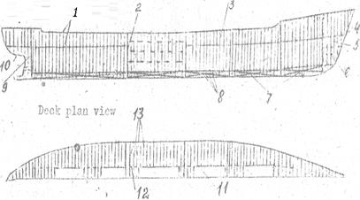
Pic. 26. General arrangement of framing
1. Deck; 2. Transverse bulkhead; 3. Side frame; 4. Stem; 5. Forepeak; 6. Side stringer; 7. Double bottom; 8. Floor; 9. Afterpeak; 10. Sternpost; 11. Hatch; 12. Carling; 13. Deck beam
Properly the hull consists of the framing and shell. The shell is subdivided into a bottom shell, side shell and deck plating. The framing and the shell are the main structural members of the hull. They include the following members.
a) bottom framing and shell;
b) side framing and shell;
c) deck framing and deck plating.
Typical superstructures are.
1. The forecastle in the forward part of the ship which begins from stem;
2. The bridge is located amidships. The designation of the bridge is to protect the ship from getting water through openings in the machine and other castings.
3. The poop is a superstructure in the aft to protect the rudder arrangement and to cover the machine and boiler castings if they are arranged in the stern.
4.
The space between all these superstructures of the upper deck is usually protected by with bulwarks.

Pic.27. Section of dry cargo ship
1. Deck Beam; 2. Upper deck plating; 3. Deck stringer; 4. Beam knee; 5. Sheer strake; 6. Frame; 7. Second deck plating; 8. Ice strake; 9. Tweendeck; 10. Third deck plating; 11. Hold; 12. Bilge bracket; 13. Bilge strake; 14. Margin plate; 15. Floor; 16. Tank top; 17. Keelson; 18. Garboard strake; 19. Flat plate keel; 20. Vertical keel; 21. Side hatch coaming
Subdivision members of the ship serve to provide unsinking of the ship, fire- proof safety and the strength of the ship. Subdivision members are accomplished with the arrangement of decks and partial decks and with the arrangement of transverse and longitudinal bulkheads. They make compartments of the two kinds. decks of the hull and decks of the superstructures. Decks of the hull are as follows. (1) upper deck, (2) middle deck, (3) lower deck and (4) platform.
The decks of superstructure are the following. (1) bridge deck, (2) lower promenade deck, (3) upper promenade deck and (4) boat deck.
Taking into consideration all this the hull construction of a modern vessel is composed of (1) longitudinal framework, keel, keelsons, stringers, deck girders, longitudinal bulkheads, hull and deck plating; and (2) transverse framework, beams, transverse bulkheads, wooden deck, etc. As for the external shell plating and deck plating they also stiffen the hull transversely. At interconnections of longitudinals and transversals additional ties are introduced such as in the form of brackets and straps.

Pic. 28. Transverse bulkhead.
1 – stiffener; 2 – shelf plate
Rigidity stability and permanent depth of hull is guaranteed by floors, side plating longitudinal and transversebulkheads as well as by pillars. Local rigidity at the ends of the hull is also secured by stem and stern.
Последнее изменение этой страницы: 2016-07-27
lectmania.ru. Все права принадлежат авторам данных материалов. В случае нарушения авторского права напишите нам сюда...